
PLC Programming Examples on Industrial Automation

 Develop PLC Programming Examples on Industrial Automation according to the logic given below,

  1. A Saw, Fan and oil pump all go ON when a start button is pressed.
  2. If the saw has operated less than 20s, the oil pump should go off when the saw is turned off and the fan is to run for an additional 5s after the shutdown of the saw.
  3. If the saw has operated for more than 20s, the fan should remain on until reset by a separate fan reset button and the oil pump should remain on for an additional 10 s after the saw is turned off.
  4. Write a program that will implement this process.

PLC Programming Examples

Program Description:
Rung 0000:
Start/Emergency Stop PB latched with memory B3:0/0.
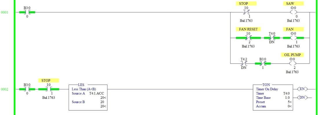
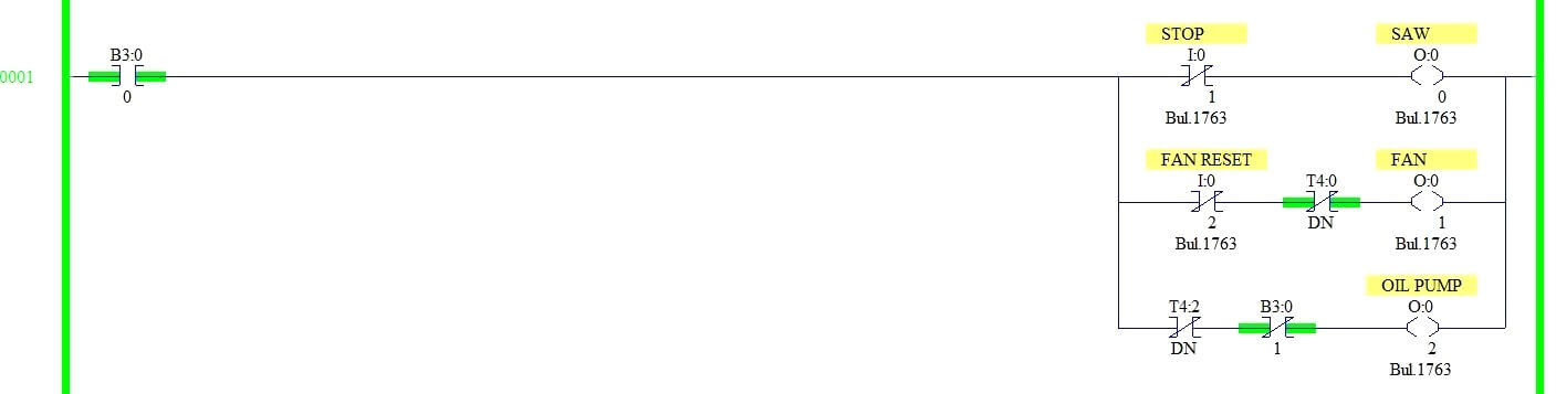
Rung 0001:
B3:0/0 enabled to turn on Saw (O: 0/0), Fan (O: 0/1 ) and Oil pump (O:0/2).

Normally closed contact of Stop switch is in series Saw output to turn off.

Fan reset switch and Timer T4:0 is connected to turn off Fan when condition meets.

Timer T4:2 done a bit and memory bit is to turn off the oil pump.

Rung 0002:
When the stop is pressed, according to the logic mentioned in point 2, Fan output (O: 0/2) needs to turn off after 5s.

Comparator block restricts the timer T4:0 to run after the 20s of Saw operation.

Rung 0003:
Timer T4:1 runs when the start is pressed. When the stop is pressed at any point after the 20s, Saw output will go off.

After 10s, the oil pump will go off. This operation is done by Timer T4:2. Timer T4:0 done bit is used to restrict the Timer T4:1 operation when T4:0 is ON.

Rung 0004:
Less than a comparator block is used to perform the logic mentioned in point 2, to turn off Fan when saw output operation was less than 20s.

Program Output:
Now we see the simulation of above ladder logic for different conditions as mentioned below.

When Start PB is pressed
When Stop switch pressed before the 20s

When Stop switch pressed after the 20s
When Fan reset switch is pressed

Conclusion:
We can use this example to understand the programming logic in Allen Bradley PLC.

-END-

Comments

Popular posts from this blog

What is a Torbar? – Averaging Pitot Tubes

 The Torbar is employed for flow measurement of liquids, gases, or steam in circular, square, or rectangular section ducts for large flow rates. The Torbar is an insertion type multi-port self-averaging primary sensor for flow measurement. Torbar TORBAR is a set of Pitot tubes mounted on a bar across the pipeline with no moving parts. An averaging Pitot tube is a technology, while TORBAR is a manufacturing brand name. There are several brands available in the market with VERABAR, ANNUBAR, etc. Averaging Pitot Tube Principle Purpose Averaging Pitot tube can be employed when the average velocity of the flow profile, rather than the velocity in a specific point in the cross-section is desired. Averaging Pitot Tubes Principle It measures the differential pressure between the static pressure tap and the tap of full pressure of a stream. Thus such magnitude of differential pressure is directly proportional to the square of the flow rate. Working The TORBAR is designed in such a way that ...

Ferrules and Cross Ferruling

 Ferrules are identification labels provided for every wire terminations in an instrument, equipment, or electrical/instrumentation control panels. These tube-shaped sleeves can be inserted easily on each individual wire in a multi-core cable. In earlier days fixed digits/letters are used as ferrules, but now Instrumentation engineers/technicians prints out desired ferrules by using a ferrule printing machine. Typical Ferrule The numbers/ letters on the ferrules will be given as per the approved electrical hook up or loop diagrams. This helps technicians to easily identify a particular loop/wiring from a series of terminal blocks and to troubleshoot the desired terminal connection. Separate numbers on the ferrules distinguish the positive and negative polarities of wires, thus ensure the polarity protection of the instrument. Cross Ferruling  As a wire is connected on its both ends, it is quite useful to use a cross reference method for wire identification. Unlike normal ferru...

Thermowell Insertion and Immersion Length

 The thermowell is the industrial housing for temperature elements like RTD or thermocouple or temperature gauges. Thermowell is directly exposed to process fluid/media. Inside the thermowell, element/gauge is installed. Thermowell transfers the heat to the temperature element. Depending upon the element type, the fluid temperature can be known. So Thermowell protects the temperature element against harsh conditions and process fluid. It enables removal of the temperature element for replacement, repair, or testing without affecting the process system. Generally, thermowells are provided with all-temperature Elements like RTD or Thermocouple or temperature gauge. A few exceptions would be bearing RTD, skin type thermocouple, air duct thermometer, etc where thermowell is not applicable / required. When the thermowell assembly is inserted into the pipe, it is subjected to vibration. This vibration is caused by vortices to be generated alternately on either side of the thermowell. The...