Ultrasonic Level Transmitter Principle, Limitations, Calibration and configuration

 Measurement principle

Continuous non‐contacting ultrasonic level measurement is based on the time of flight principle.

An ultrasonic level instrument measures the time between sound energy transmitter from the sensor, to the surface of the measured material and the echo returning to the sensor.

As the speed of sound is known through the travel medium at a measured temperature, the distance to the surface is calculated. Level can be calculated from this distance measurement.

Echo Processing built in to the instrument can allow the instrument to determine the material level of liquids, solids or slurries even in narrow, obstructed or agitated vessels.

Limitations

Ultrasonic is seldom used in upstream hydrocarbon process stream for level measurement; it might be used in atmospheric utilities applications. In applications which are susceptible to vapour density variation, compensation reference pin should be used.

Maximum measurement distance should be checked against the technology (above 30 m the reflectivity may be reduced and might cause a measurement error/problem).

Ultrasonic sensors have, as physical limitation, a blocking distance (close to the sensor) where they cannot measure reliably, e.g. 0.25 metres.

Vessel pressure limitation should approximately be, e.g. 0.5 bar or less. Higher pressure may introduce uncertainty in the level measurement.

Vapour, vacuum or temperature gradients can influence the speed of sound and consequently can cause incorrect measurements.

Presence of foam or heavy turbulence on the surface of the measured material can cause unreliable measurement.

Selection

As ultrasonic is non‐contacting, even abrasive or aggressive materials can be measured. Vessel height and head room should be considered to select an instrument with suitable minimum and maximum range.

Design

Ultrasonic sensors should be made of a material suitable for the measured medium (e.g. PVDF or ETFE) Solid construction and a self‐cleaning action on the face of the sensor provide a reliable, low maintenance product.

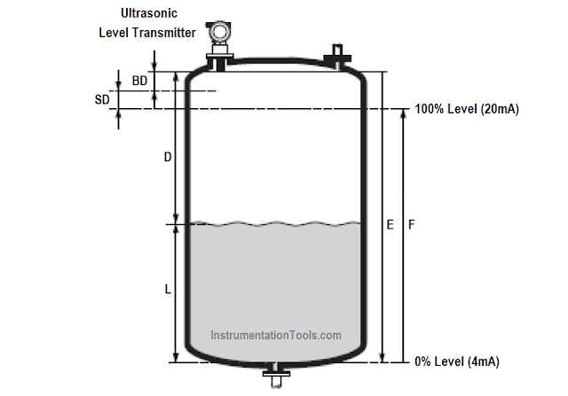
Figure – Ultrasonic Liquid Measurement Arrangement.

Use of a submergence shield on a sensor will allow an ultrasonic instrument to operate in potential flooding conditions reporting a full vessel to a control system or continuing to operate pumps to remove the flood condition.
Figure – Ultrasonic Level Transmitter calibration

  • BD : Blocking Distance
  • SD : Safety Distance
  • E : Empty Calibration ( Zero Point )
  • F : Full Calibration ( Span )
  • D : Nozzle Diameter
  • L : Level
Performing an initial or ‘empty calibration’: In this principle, ‘enter’ the distance E from the sensor face to the minimum level (zero point). It is important to note that in vessels with parabolic roofs or bottoms, the zero point should not be more distant than the point at which the ultrasonic wave reflects from the tank bottom.

When possible, a flat target plate that is parallel to the sensor face and directly below the sensor mounting position should be added to the bottom of the vessel for best empty tank performance.

Once the empty distance has been set, the high calibration point or 100% full point can be set. This is done either by setting the distance from the sensor face to the 100% full level or by entering a span (level) from the 0% or low calibration point to the 100% full level.

During commissioning, ensure that the 100% full or high calibration point does not enter the ‘blocking distance’ or ‘blind zone’ of the respective sensor. This will vary from sensor to sensor. Blocking distances or blind zones can be extended to avoid false high level reflections caused by obstructions, but they can only be reduced to a certain distance due to the physical limitations of the sensor itself. The minimum level (distance E/zero point) should be configured. This zero point should be above any dished boiler heads or conical outflow located at the bottom of the tank/vessel.

The maximum level (distance F/full span) should be configured. This distance F should take into account both BD ‘blocking distance’ and SD ‘safety distances’.

Where BD represents a dead zone in which the wave cannot make any measurement and SD corresponds to a warning or an alarm zone.


Comments

Popular posts from this blog

Ferrules and Cross Ferruling

 Ferrules are identification labels provided for every wire terminations in an instrument, equipment, or electrical/instrumentation control panels. These tube-shaped sleeves can be inserted easily on each individual wire in a multi-core cable. In earlier days fixed digits/letters are used as ferrules, but now Instrumentation engineers/technicians prints out desired ferrules by using a ferrule printing machine. Typical Ferrule The numbers/ letters on the ferrules will be given as per the approved electrical hook up or loop diagrams. This helps technicians to easily identify a particular loop/wiring from a series of terminal blocks and to troubleshoot the desired terminal connection. Separate numbers on the ferrules distinguish the positive and negative polarities of wires, thus ensure the polarity protection of the instrument. Cross Ferruling  As a wire is connected on its both ends, it is quite useful to use a cross reference method for wire identification. Unlike normal ferru...

PLC Program for Mixing Tank

 Create a ladder diagram for controlling a batch mixing process. Implement a PLC program for mixing tank or Mixing Process using PLC Ladder Logic. PLC Program for Mixing Tank Fig : Mixing tank A tank is used to mix two liquids. The required control circuit operates as follows: A. When the START button is pressed, solenoids A and B energize. This permits the two liquids to begin filling the tank. B. When the tank is filled, the float switch trips. This de-energizes solenoids A and B and starts the motor used to mix the liquids together. C. The motor is permitted to run for 1 minute. After 1 minute has elapsed, the motor turns off and solenoid C energizes to drain the tank. D. When the tank is empty, the float switch de- energizes solenoid C. E. A STOP button can be used to stop the process at any point. F. If the motor becomes overloaded, the action of the entire circuit will stop. G. Once the circuit has been energized, it will continue to operate until it is manually stopped. Solution...

What is a Torbar? – Averaging Pitot Tubes

 The Torbar is employed for flow measurement of liquids, gases, or steam in circular, square, or rectangular section ducts for large flow rates. The Torbar is an insertion type multi-port self-averaging primary sensor for flow measurement. Torbar TORBAR is a set of Pitot tubes mounted on a bar across the pipeline with no moving parts. An averaging Pitot tube is a technology, while TORBAR is a manufacturing brand name. There are several brands available in the market with VERABAR, ANNUBAR, etc. Averaging Pitot Tube Principle Purpose Averaging Pitot tube can be employed when the average velocity of the flow profile, rather than the velocity in a specific point in the cross-section is desired. Averaging Pitot Tubes Principle It measures the differential pressure between the static pressure tap and the tap of full pressure of a stream. Thus such magnitude of differential pressure is directly proportional to the square of the flow rate. Working The TORBAR is designed in such a way that ...